Table of Contents
Plotter and Exporter
The Plotter and Exporter tool can be used to export selected views and/or sheets from a Revit project to any of multiple formats, including PDF, DWG, DXF, DGN, DWF/DWFx and for 3D views, to Navisworks, IFC and FBX.
It can also print selected views and/or sheets to a printer or plotter, or export an entire model to a Navisworks or IFC file.
Additionally, it can be used to take “snapshot” files for the CTC Model Compare tool, which is available in the CTC BIM Project Suite. It extracts data from a project and saves it in a “snapshot” file, then can compare the differences between two snapshot files, showing how the project had changed during the time between when each snapshot file was created.
Further, Plotter and Exporter can be configured to do any of these plots or exports on a schedule. For example, it could be configured to export PDFs every week night, and/or once a week, and/or once a month, etc. The nature of plotting or exporting can be a very complicated process. For example, there can be many settings to configure for an export.
A primary goal of this tool is to make the process of plotting or exporting as simple and easy as possible for the daily Revit user, while still providing a lot of flexibility. To help achieve this goal, the minimal amount of information needed is presented at a time.
A significant feature of Plotter and Exporter is that it ships with a free PDF printer driver, called the “CTC PDF Writer” which can not only be used with Plotter and Exporter but other software as well, such as Microsoft Office products.
NOTE: As of this writing, Plotter and Exporter has been developed and tested against the following PDF drivers:
- CTC PDF Writer (Free! Comes with the suite.)
- Adobe Acrobat DC
- Bluebeam Revu
- PDFCreator (Paid version only)
- PDF995 (Paid version only)
It may work with other PDF drivers as well, but only limited support is available for the drivers listed above. If you are a system administrator, detailed configuration options for Plotter and Exporter are documented in the CTC Suites Installation and Configuration guide.
Starting Plotter and Exporter
Click the PE button on the CTC Batch Suite panel located within the CTC Software tab:
![]()
The Plotter and Exporter Interface
When starting Plotter and Exporter for the first time, the main configuration window will appear:
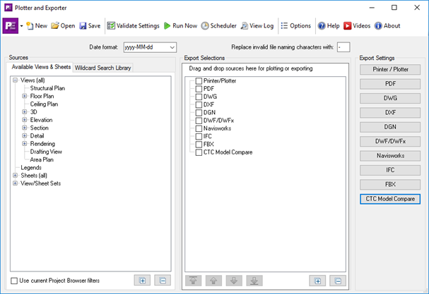
This window is used to define what to export and how to export it. These configurations can be saved as Plotter and Exporter Configuration files (*.peconf) and later reloaded for editing.
What to export is selected from the “Sources” column on the left, to which formats to export are chosen in the “Export Selections” column in the middle, and where to export them to and what settings to use are defined by the format-specific buttons in the “Export Settings” column on the right.
The list of all the views and sheets in the current project will appear in the “Available Views & Sheets” list. Note that this list can be filtered down by applying the current Project Browser filters by using the “User current Project Browser filter” checkbox below the list.
An important advantage of this approach is that one configuration file can be applied to more than one Revit project file. The use of wildcard view or sheet searches (discussed below) is a powerful tool for helping facilitating this.
One could, for example, define a configuration file for:
- Creating PDFs for any of their hospital projects, or
- Creating DWGs just for all of the mechanical views in any of their office building projects, or
- Printing all of the sheets for the highest issued revision for any project
Quick Start Example Workflow
Before explaining the details and options available, we’ll start with a very simple example to quickly provide a feel for the overall workflow. In this example, we will create DWG files from some sheets.
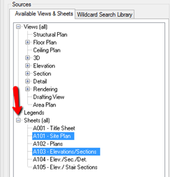
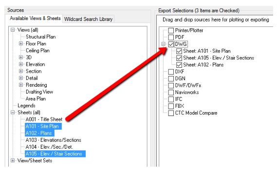
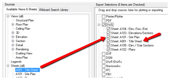
Start by expanding the “Sheets (all)” node in the Sources column. This will show the list of sheets defined in this project. In our example, we want to export sheet A101 and sheet A103, so we’ll click on sheet A101 and hold down the Ctrl key while clicking on A103, to select only those sheets:
Now we simply drag-and-drop the selected sheets over to the “DWG” entry in the list in the middle:
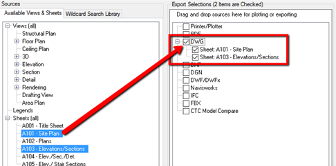
Plotter and Exporter will assume they should both be included in the export, and will place checkmarks in the checkboxes for them automatically. Only items with checkmarks next to them will be included in the next plot or export.
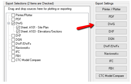
Before we can export these sheets to DWG files, we must configure the DWG settings. This is done by clicking on the “DWG” button in the right column, which will open up the DWG-specific settings:
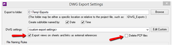
The DWG settings screen initially looks like this:
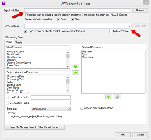
While default settings are provided for most things (and will be explored in more detail later), the two fields that must be specified are the folder in which to put the exported files, and which DWG export settings should be used. For now, we’ll select an existing folder on our local C: drive (C:\Temp\Exports) and for the DWG settings we’ll select the “`<custom export settings>` “ choice, which is always available. These custom settings are specific to the configuration file we’re defining, and always start out with valid default values which can successfully produce DWG files.
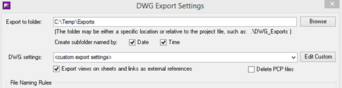
Note that with the above settings a subfolder within C:\Temp\Exports will be created that is named by the date and time of whenever the export happens. Also note that the PCP files that are generated will not be deleted.
Click the “OK” button on this screen to return to the main configuration screen.
At any time on the main configuration screen the “Validate Settings” toolbar button can be clicked. If there are any errors or warnings with the current configuration they will be presented in a list.

Clicking this button now shows:
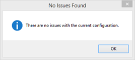
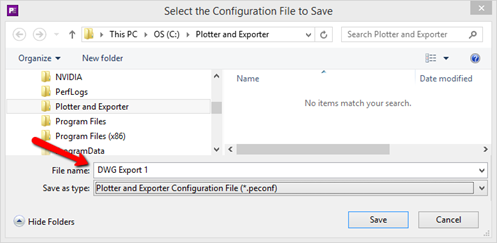
This means we are ready to export. Before we do that, we should save our settings so we can reuse them again later on this project or any other project. Do this by clicking the “Save” button in the toolbar:

We’ll store this configuration file in a local folder (C:\Plotter and Exporter) and call the file “DWG Export 1.peconf” –
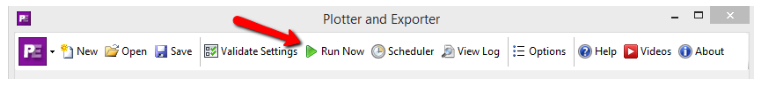
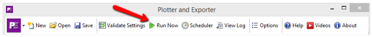
Next, click the “Run Now” button on the toolbar:
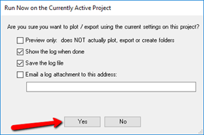
The “Run Now” window will appear, with some options. Just click “Yes” to start the export.
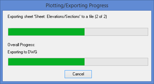
During the export, a progress dialog will appear which will allow canceling the export:
Once the export is complete, the log showing what happened will appear:
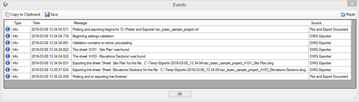
Warnings and errors may also appear in this list, with different colored icons.
If we look in the C:\Temp\Exports folder we’ll find a date- and time-stamped subfolder, and in that folder we can see the exported files.
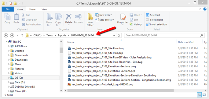
The “extra” dwg and pcp files exist because the default settings which control those were set that way:
Selecting Views and Sheets by Name (and View Type) Views and sheets can be specified for plotting or exporting by simply dragging and dropping them from the “Available Views & Sheets” list onto the export format desired, such as PDF or DXF, in the Export Selections list.
This was demonstrated in the Quick Start example above.
While it may be intuitive to think that this only applies to the currently open Revit project, in reality when this configuration is saved it can be reapplied to any other Revit project. Views in the other project must have the same name and be of the same type in order to be exported. Sheets in the other project must have the same sheet number and sheet name to be exported. However, if projects are sourced from templates and company standards are followed, this will work.
IMPORTANT: Because the Export Selections are stored by view type and name so the configuration may be used with many projects, if you drag and drop a sheet or view into the list from the current project, close Plotter and Exporter, then renumber or rename the sheet or view in the project, the next time you perform an export it will still be looking for the sheet or view with the original number or name, and will not find it. In other words, Plotter and Exporter will not know to look for the view or sheet with the new number or name.
A more powerful way to export views and sheets from other projects is to use wildcard searches, which are discussed in the next section. This may be useful for handling some renumbering or renaming cases.
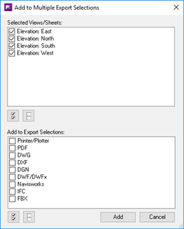
Dragging and dropping isn’t the only way to get multiple selected views and/or sheets to their export formats. Once one or more items have been selected, right-clicking on one of the selected items will display a popup menu with the choice “Add All Selected to Export Selections…” which, when selected, will display this dialog:
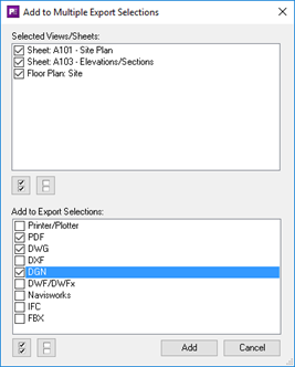
The top portion lists all the views and sheets that were selected. The bottom portion allows selecting to which export formats to add them.
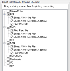
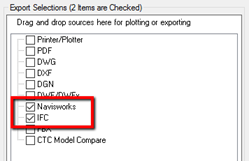
In this case, when the Add button is clicked we’ll see the following:
Regardless of how items are added to the Export Selections list, once on the list a view or sheet can be temporarily removed from the export by simply unchecking it.
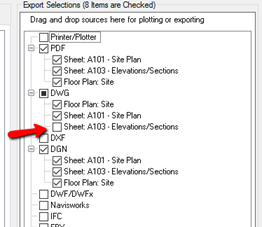
For example, if in the next export we don’t want to include sheet A103 in the DWG export, we can still leave it in the list but exclude it from export by unchecking it:
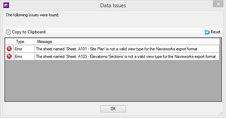
IMPORTANT: Not all export formats allow all views and sheets to be dropped onto them. For example Navisworks, IFC and FBX can only have 3D views dropped on them.
If invalid views are dropped, an error message will occur. For example, in a new project if we choose to drop all the 3D views and 2 sheets onto the Navisworks export format, the following dialog would appear:
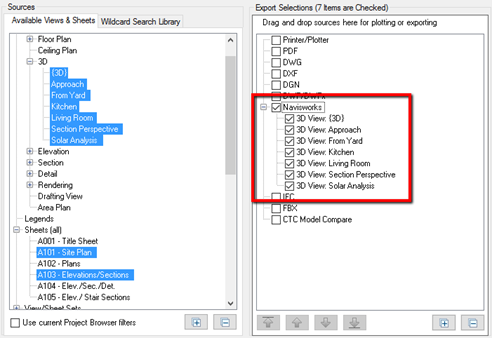
But when the OK button is clicked, all of the 3D views would be successfully added to the Navisworks export format:
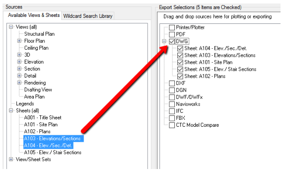
Another way to get all of the current views for a view type to an export format is to drag the view type itself from the Sources list to the export format desired. For example:
Yet another way to get all the current views for a view type to one or more export formats is to right-click on the view type and select the “Add All to Export Selections…” choice:
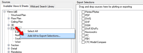
This will bring up the same dialog we saw above, allowing selecting multiple export formats to which to add all views:
While Navisworks, IFC and FBX can only accept 3D views, Navisworks and IFC have one more special feature: you can easily export the entire model.
This is done simply by checking the Navisworks and/or IFC checkboxes without putting any 3D views in their lists:
If views or sheets are specified but not in the project being exported, the log will show which ones could not be found.
Selecting Views and Sheets Using Wildcard Searches
One of the more powerful features of Plotter and Exporter is the ability to specify a search for views or sheets to include in an export. This is done using a “wildcard search” and can be particularly useful for reusing a configuration file across multiple projects.
Among other things, the wildcard search feature allows for:
- Automatically including newly-created views in the next export, without having to change the settings being applied. If the newly-created views match the search criteria, they will automatically be exported too.
- Automatically excluding newly-created views that don’t match the search criteria in the next export.
- Applying the saved Plotter and Exporter configuration file (*.peconf) to multiple project files with more dynamic meaning than just exporting by individual view- or sheet-names.
Managing Wildcard Searches
View or sheet wildcard searches can be named and saved into the Wildcard Search Library for later reuse. The Wildcard Search Library is in the second tab of the “Sources” column:
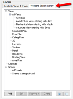
Some basic search examples are provided with Plotter and Exporter, as seen above.
Clicking the Add button at the bottom of the list will create a new wildcard search.
When one wildcard is selected in the list, the Edit button is available for editing the wildcard. Double-clicking on a wildcard search will also bring up the editor for it.
When one wildcard is selected in the list, the Duplicate button is available for copying the wildcard. The duplicate process simply begins the “Add” process, but predefines the values to be copies from the wildcard being duplicated and highlights the wildcard description as a reminder to give the new copy a different description.
When one or more wildcard searches are selected in the list, the Delete button can be used to delete them.
These are the settings for searching for all sheets whose name in the Project Browser starts with “A1” –
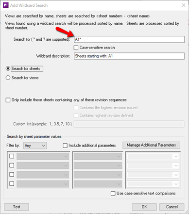
The key information is the “Search for” value. For sheets it searches the combination of sheet number and sheet name using the same basic wildcard syntax used when searching for files.
For example:
A1*– searches for all sheets whose sheet number and name combined start with A1. – searches for all sheets (name doesn’t matter)
A?00*– searches for all sheets whose sheet number and name start with A followed by any single character followed by 00 followed by anything else. So sheets A100, A200 and A300 would be selected.
*Mech*– searches for any sheet with the text “Mech” anywhere in the combination of sheet number and sheet name.
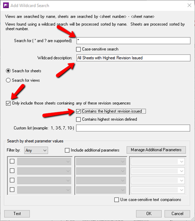
Searches can also be refined by searching by revision information. For example, these settings would find all sheets for the latest revision issued:
If instead of the highest revision issued you wanted only those sheets with revision sequence 1,2,3,6,7,8,10 or anything 14 or later, instead of having the highest revision issued checkbox checked, this Custom List would be entered instead:
-3, 6-8, 10, 14-
IMPORTANT: A very powerful feature is to search for views or sheets based on parameter values.
Just one way to do this is to define some custom yes/no project parameters which are bound to the Views and/or Sheets category. These parameters could have names such as:
- Export to PDF
- Export to DWG
- Print to Plotter
One could then create a schedule in the project for controlling which views and/or sheets are to be exported to which format by using these parameters. This allows a Revit user to control what gets exported to which formats by checking or unchecking the checkboxes that appear in the schedule.
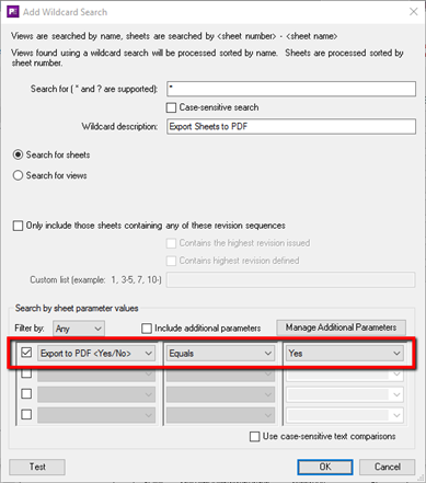
As a simple example, one could create a wildcard called Export Sheets to PDF which looks like this:
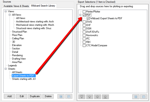
One would then add this wildcard to the PDF export selection list:
The parameter filtering works very much like the filtering used by Revit within schedules, with the additional ability to require All of the parameters to match (an “and” check, as Revit schedule filtering does) or the ability to require Any of the parameters to match (an “or” check):
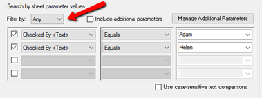
The list of parameters from which to choose (in the first column) comes from the parameters for sheets in the currently open project. The list of available choices (in the third column) consists of all the unique values found for the selected parameter in the current project. However, you can always type in any value as appropriate.
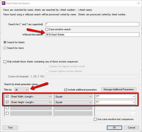
The list for sheets contains 3 special parameters:
- Sheet Width
- Sheet Height
- Title Block Name
These can be used to search for sheets of a specific size (or smaller than a specific size), for example to print to a printer that has a specific paper size available:
IMPORTANT:
- The sheets or views found in the results may be unpredictable if two or more parameters with the same name being tested exist on the views or sheets in the project. For example, if two project parameters called “View Type” exist and are both bound to the Views category, if only one of them has a value in each view and you try to filter by the “View Type” parameter value, the views reported as found may be unpredictable.
- Because Plotter and Exporter lets you create configuration files which can be applied to any project, you may need to specify parameters for the wildcard which don’t happen to be in the current project. This can be done using the “Include additional parameters” checkbox and the “Manage Additional Parameters” button.
You will not see the ability to work with additional parameters if your system administrator has turned off this feature.
The “Manage Additional Parameters” button brings up the window for editing the list of additional parameters:
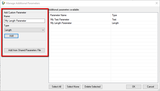
Parameters to add to the list of choices can either be typed in manually, or imported from a shared parameters file.
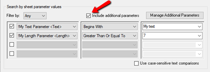
Once the “Include additional parameters” checkbox is checked, the list of parameters from which to choose will include the additional parameters as well:
If we were to try to save the above wildcard definition, we would get the following warning:
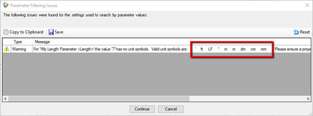
The problem occurs because we’ve specified a parameter that is of a type which has units of measure (Length), and our comparison value in the third column which we typed in did not specify units of measure.
Because some unit symbols are difficult to type in (for example, ft² ) you can copy unit symbols from the warning window and paste them into the comparison value field after the number previously entered.
A parameter filter can be kept in the list, but ignored when searching for sheets or views by simply unchecking the checkbox next to it.
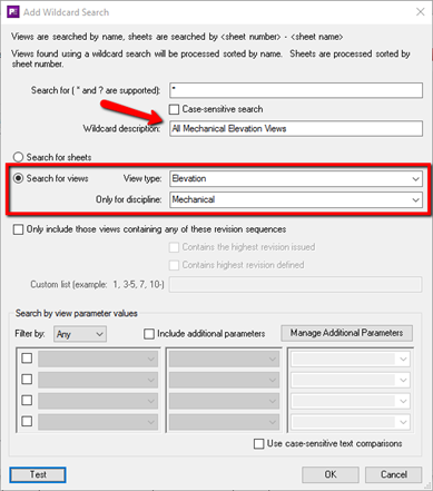
Wildcard searches for views work the same way as for sheets, with some additional options to filter by view type and/or view discipline (there are “All” choices for both View Type and Discipline as well):
Filtering views by revisions works the same way as for sheets, however to be included in the results the views must have one or more matching revision clouds on them for the filtering to work.
Filtering views by parameter values works the same way as for sheets, except the list of parameters from which to choose comes from those in the current project that are for views. The use of Additional Parameters is supported for views as well.
The “Test” button in the lower left corner will execute the search of the currently open project and show the results. For example, the results for the search to find all sheets that start with A1 may yield these results:
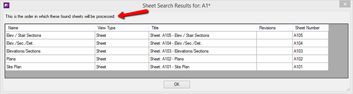
As the on-screen instructions state, the order in which the results of a wildcard search will be plotted or exported cannot be controlled, but the test results will show the order in which they’ll be processed.
Using Wildcard Searches
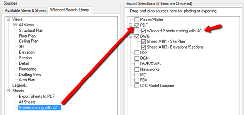
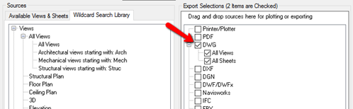
To add one or more wildcard searches to an export format, such as PDF, simply select them from the library and drag and drop them onto the export format top-level item in the Export Selections list (e.g. the “PDF” item).
IMPORTANT: Once a wildcard from the library is dropped onto the export format, it becomes a copy of the wildcard defined in the library. Changing the definition in the library WILL NOT change its settings in the Export Selections list.
This makes it easy to start with a wildcard from the library and make fine-tuning changes to it that only apply to the current configuration file being edited, for example changing parameter values. These changes can be made by simply double-clicking on the wildcard in the Export selections list, which will bring up the editor for that copy in the list.
There is also a shortcut way to get wildcards in the list for an export format, provided there are no views or other wildcards already in the list for that export format: simply checking an empty export format checkbox will add two “all” wildcards, one for all views and one for all sheets:
Of course, double clicking on either of these automatically-added wildcards will allow editing them, including changing their name.
As with dragging views or sheets into the list, wherever you drop a wildcard from the library it will be added to the Export Selections list immediately after the item on which it was dropped. Also as is the case with views or sheets, once in the Export Selections list it can later be moved up or down the list using the arrows below the list. This is explained in more detail, below.
Selecting Views and Sheets Using View/Sheet Sets
Within the printing section of Revit you can defined named selections of views and sheets. Those available will appear in the Sources list under the “View/Sheet Sets” section:
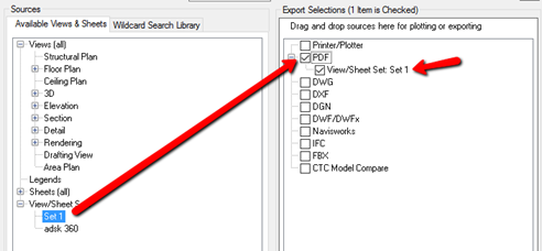
When the export is run against any project, it will look for a View/Sheet Set with the name specified in the settings.
In the example above, the views and/or sheets that will be exported to PDF will be whichever views and/or sheets are specified in the set whose name is “Set 1” in the project. If there is no View/Sheet Set named “Set 1” in the project being exported, then this item is skipped during the export.
List Pop-Up Menus
Each of the lists on the main configuration screen have context-sensitive right-click pop-up menus. The menus are different depending on where you right-click, and the choices available will vary based on (for example) whether or not any sub items are selected, or the item itself is selected.
The three right-click “zones” are:
- The white space
- An upper-level item
- A lower-level item
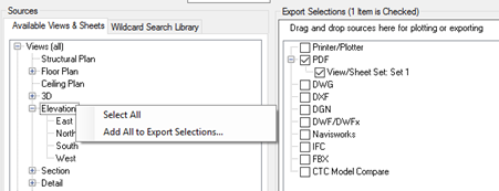
For example, right-clicking in the white space of the “Available Views & Sheets” list while no items are selected will produce a pop-up menu that looks like this:
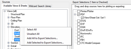
However, right-clicking in the white space while some items are selected shows more choices:
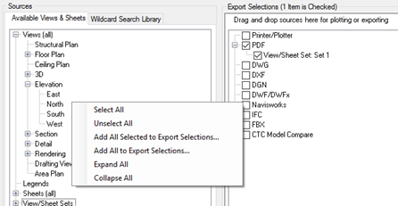
Right-clicking while on the upper-level “Elevation” item in this list (while no sub-items are selected) shows:
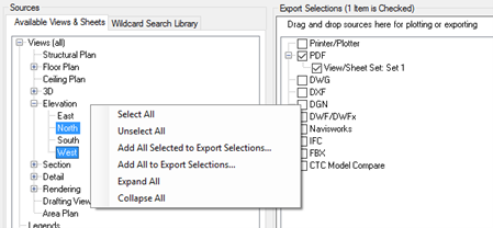
However, when some of the sub-items are selected, we again see more choices when right-clicking on the Elevation item:
Right-clicking while on the “North” lower-level item in this list (while it’s not selected) shows:
While it would be tedious to list every possible pop-up menu combination for every list and state of items in the list, you should now have an awareness that the pop-up menu choices vary depending on where you right-click, which item you right-click on (if any), whether or not that item is selected, and the state of any sub-items for that item.
Controlling the Order of Export Selections
Items in the “Export Selections” list will be processed in the order in which they appear in the list. The order in which an export format’s sub-items are processed can be controlled.
For example, this may be particularly useful if you want to control the order of the pages in a PDF document that is to be created from more than one view and/or sheet.
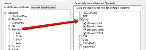
The first way to control the order is when selecting multiple views or sheets to drag and drop onto an export format, such as DGN. When using the Ctrl key to multi-select individual sheets, the order in which they are selected will be the order in which they’ll appear in the Export Selections list.
In this example, the red numbers indicate the order in which the selected sheets were added when using the Ctrl key for multiple item selection. When dragged to the “DGN” export format, they appear in the same order.
If a selection is dropped on the “DGN” item directly, it will appear in the list immediately below the “DGN” item. For example:
If a selection is dropped on a sub-item, it will be added to the list immediately after that sub-item. For example:
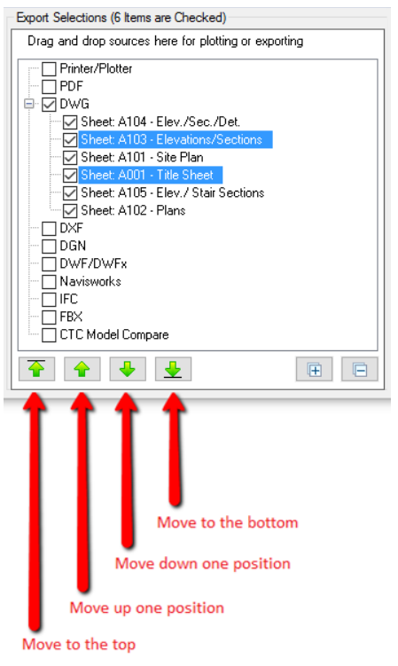
Once a list of sub-items has been created, the order for one or more selected sub-items can be controlled using the buttons located below the list.
Global Export Settings
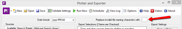
The global settings affect all export formats. There are only two global settings, seen at the top of the main configuration screen:
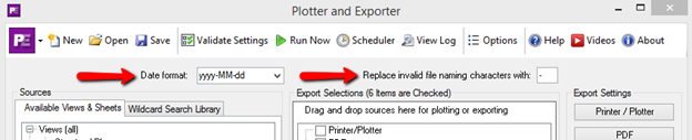
The “Date format” is used whenever a folder name or a file name is created which uses a date value. Although a list of choices is provided, you may also type in your own custom date format to use.
The “Replace invalid file naming characters with” is a text character that should be used whenever an invalid file name character would be used when generating a file name.
As we’ll see shortly, filenames for export files can be generated based on view- or sheet- parameter values. As these values may have characters that can’t be used in filenames, the character specified here will be used instead wherever that may occur. It is acceptable to have no character used here, which would simply remove invalid characters from the file names generated.
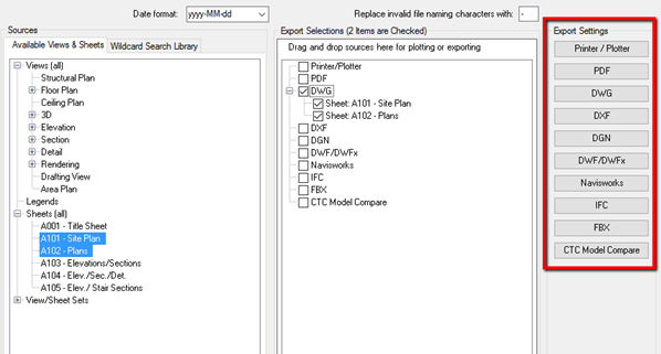
Export Format-Specific Settings
Once an export format (such as PDF or DWG) has something configured for export, the format-specific settings must be configured as well. Accessing these settings is done using the format-specific buttons in the right-most column:
Common Settings
Most export formats have some common settings, which include defining where to put the export files to be created, and how to name the export files to be created. These settings are highlighted in the image below.
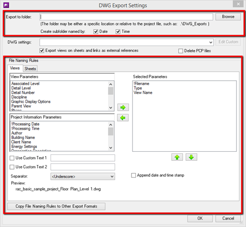
“Export to folder” determines where the files to be exported will be placed. This can be a specific folder (e.g. “C:\Exports”) or it can be a folder that is located relative to where the project file being processed is located.
Note that in the examples below, if either the “Date” or “Time” checkboxes are checked, one more subfolder would be created (named by a date- and/or time-stamp of when the export takes place) in the results.
Relative path example 1:
Use a subfolder within the project’s folder
Project file location: P:\Projects\Hospitals\Hospital1\Hospital1.rvt
“Export to folder” value: .\DWG_Exports
Resulting folder for exports (created if needed): P:\Projects\Hospitals\Hospital1\DWG_Exports
Relative path example 2:
Use a folder at the same level as the project’s folder
Project file location:P:\Projects\Hospitals\Hospital1\Hospital1.rvt
“Export to folder” value: ..\DWG_Exports
Resulting folder for exports (created if needed): P:\Projects\Hospitals\DWG_Exports
Relative path example 3:
Use a folder at a higher level than the project’s folder
Project file location: P:\Projects\Hospitals\Hospital1\Hospital1.rvt
“Export to folder” value: ..\..\DWG_Exports
Resulting folder for exports (created if needed): P:\Projects\DWG_Exports
“File Naming Rules” determine how the exported files to create will be named. There are different “modes” for which naming rules must be configured:
- For view exports
- For sheet exports
- For “combined” exports
A combined export occurs when it’s desirable to have all the views/sheets (or the entire model) export to a single file. This occurs for example when exporting the entire model to a single Navisworks file, or if exporting multiple selected views and/or sheets to a single PDF file.
Some export formats, such as for DWG, DXF and DGN only allow creating view-specific or sheet-specific export file. There is no option for creating a “combined” single export file. This can be seen in the image above, where there are separate naming rules for views and sheets for the DWG settings. Examples of “combined” file naming settings will be demonstrated later, when the export format-specific settings are explored.
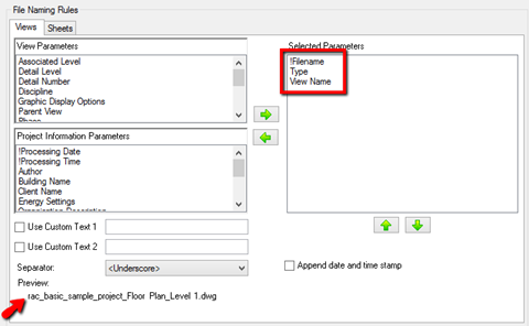
File names for view exports to separate files can be generated using any combination of view-specific parameter values and/or project information parameters plus up to two custom text values, all of which can be in any order.
File names for exports to a combined single file can be generated using any combination of project information parameters plus up to two custom text values, all of which can be in any order.
By default, when a new configuration is created a set of standard parameters are pre-selected which should create unique filenames for each view or sheet export file generated.
For views, we can see that it’s the combination of project file name, then view type, then view name. A preview of what a sample file name might look like can also been seen in the lower left corner.
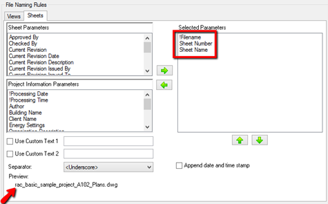
For sheets, we can see that it’s the combination of project file name, then sheet number, then sheet name. Again, a preview of what a sample file name might look like can be seen in the lower left corner.
For combined files, the default is to only use the project file name.
Exploring these dialogs further, custom text can be stored and used in the filename as well:
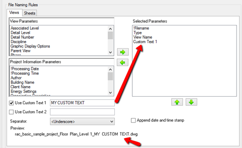
Further, the order of the parameters used in defining the file name can be changed by selecting one or more items in the “Selected Parameters” list and then using the Move Up or Move Down buttons that are located below the list. For example, if we wanted our custom text to be the first part of the name (a prefix) simply click on the “Custom Text 1” item in the list and use the “Move Up” arrow to move it to the top of that list:
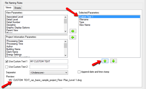
Either Custom Text value can be used as a file name prefix, suffix, or be used anywhere in the middle of the filename.
Here’s an example from the Sheets tab:
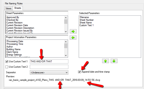
In this example, an illegal filename character (the “/”) is used in the custom text that was entered. You may notice that in the Preview this character has been replaced with a hyphen (“-“). This is the result of applying the global setting rule from the main configuration page:
In the above example the “Append date and time stamp” is also now checked, and can be seen in the Preview as well.
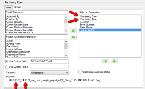
It is also possible to put the date- and/or time-stamp into the file name either together or separately, and in different locations within the file name. This is done using the two special parameters listed in the “Project Information Parameters” list, called “!Processing Date” and “!Processing Time.”
File names could, for example, be prefixed with the processing date and time by putting these two parameters at the top of the list. For example:
One final note about the file naming rules: once you have set up the rules for an export format, such as for DWG, you can easily copy these rules, as applicable, to other export formats. This is done using the “Copy File naming Rules to Other Export Formats” button, located below these settings. The dialog for that looks like this:
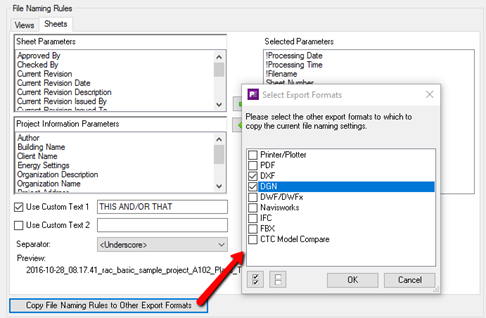
This will only copy the settings that exist for the other export formats. For example, the Navisworks export only uses “combined” or view-specific file naming rules, whereas DWG settings only use view- and sheet-specific naming rules.
Printer/Plotter-Specific Settings
The settings for sending views and/or sheets to a printer or plotter can be seen here:
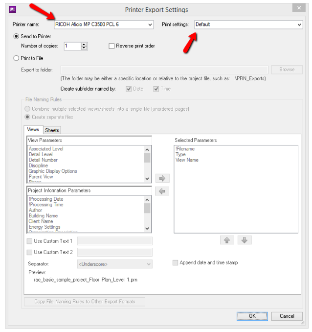
A list of (non-PDF) printers that are installed are provided from which to choose, as are the list of available print settings as defined in the currently open project.
IMPORTANT: The Printer Name and Print Settings dropdown lists are type-able. While the lists will show you what is available in the currently open project, you can also freely type in whatever printer name and print settings name should be used. This may be helpful if you plan to save this configuration and use it on other Revit project files which have that other print settings name in it, or on another computer which has that other printer with that printer name installed.
When printing to a printer or plotter, the number of copies can be controlled as well as whether or not to output the views and/or sheets in the reverse order from the Export Selections list.
Although not nearly as common, Plotter and Exporter will allow generating files using the installed printer driver instead of sending the selected views and/or sheets to the plotter or printer. This may be useful if you have an outside print service that provide a printer driver and you need to create files you can send to them for printing.
This is activated by checking the “Print to File” checkbox. Here’s an example that exports the selected views and/or sheets to a single file:
PDF-Specific Settings
The settings for exporting views and/or sheets to PDF files can be seen here:
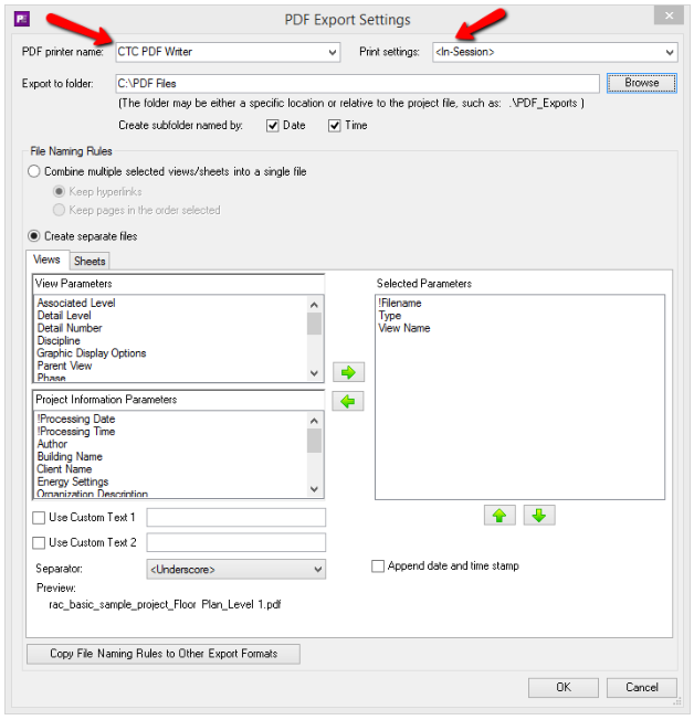
IMPORTANT: The PDF Printer Name and Print Settings dropdown lists are type-able. While the lists will show you what is available in the currently open project, you can also freely type in whatever PDF printer name and print settings name should be used. This may be helpful if you plan to save this configuration and use it on other Revit project files which have that other print settings name in it, or on another computer which has that other PDF printer with that printer name installed.
This is what it looks like when the “Combine multiple selected views/sheets into a single file” choice is selected:
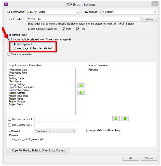
Once this option is selected, the way files can be named changes, but also you must specify whether to keep hyperlinks within the generated PDF file *or* whether to force the pages that are generated to be in the order they were specified in the “Export Selections” list on the main configuration screen.
When keeping hyperlinks, the pages may not come out in the order they were selected on the main configuration screen. This is identical to how Revit natively exports to a single PDF file. If keeping the order of the pages intact is more important than keeping hyperlinks in the document, then the “Keep pages in the order selected” option should be chosen instead.
DWG-Specific Settings
The settings for exporting views and/or sheets to DWG files can be seen here:
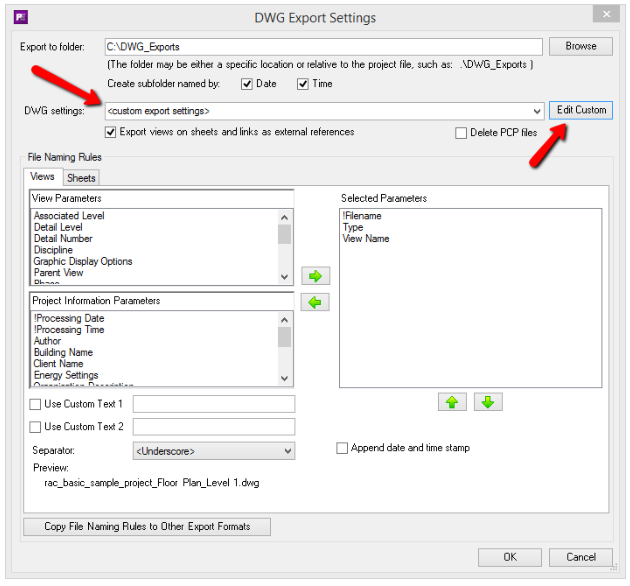
IMPORTANT:
- The DWG Settings name dropdown list is type-able. While the list will show you what is available in the currently open project, you can also freely type in whatever DWG settings name should be used during the export. This may be helpful if you plan to save this configuration and use it on other Revit project files which have that other DWG settings name already in them.
- The “
<custom export settings>” choice is always available. When this choice is selected, the “Edit Custom” button to the right becomes available. This will allow you to edit custom DWG settings that are saved in this configuration file. The custom settings always start with default settings that will at least produce valid DWG files.
* Using “ <custom export settings> ” *has an advantage*: The export settings to use go with the Plotter and Exporter configuration file, regardless of which Revit project file is being exported. This takes the concern out of having slightly different settings defined in each project when identical outputs for all projects are desired. It also takes the concern out of things such as misspelled settings names in some projects (resulting in “settings not found” errors during the export), or having other projects where the settings desired have never been saved.
Clicking the “Edit Custom” button displays the Custom DWG Settings screen:
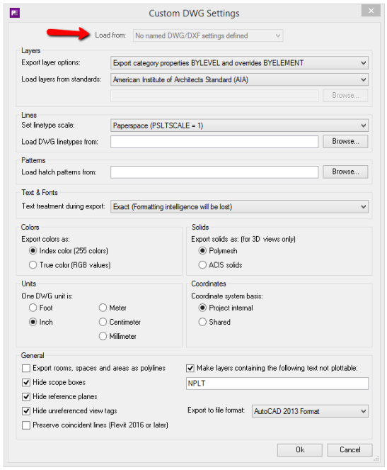
Although this project did not have saved DWG settings, if it did, the “Load from” list at the top would have been available. When selecting named settings from this list, it will ask you to confirm loading these settings from the current project AS A COPY. Once loaded they will be displayed in this dialog, and can then be edited and saved as part of the current Plotter and Exporter configuration file, which can then be applied to any Revit projects.
DXF-Specific Settings
The settings for exporting views and/or sheets to DXF files can be seen here:
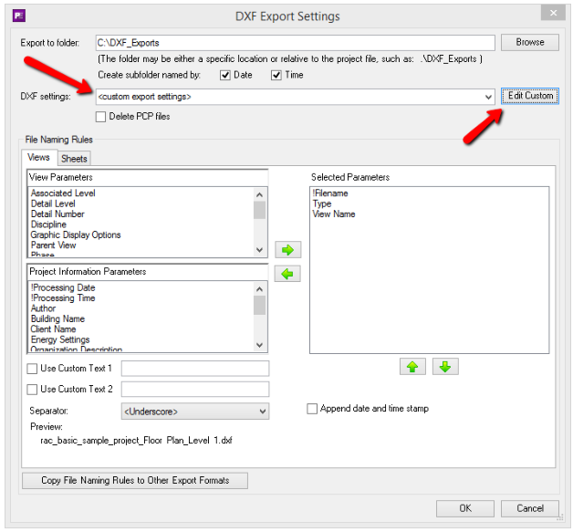
IMPORTANT:
- The DXF Settings name dropdown list is type-able. While the list will show you what is available in the currently open project, you can also freely type in whatever DXF settings name should be used during the export. This may be helpful if you plan to save this configuration and use it on other Revit project files which have that other DXF settings name already in them.
- The “
<custom export settings>” choice is always available. When this choice is selected, the “Edit Custom” button to the right becomes available. This will allow you to edit custom DXF settings that are saved in this configuration file. The custom settings always start with default settings that will at least produce valid DXF files.
- Using “
<custom export settings>” *has an advantage:* The export settings to use go with the Plotter and Exporter configuration file, regardless of which Revit project file is being exported. This takes the concern out of having slightly different settings defined in each project when identical outputs for all projects are desired. It also takes the concern out of things such as misspelled settings names in some projects (resulting in “settings not found” errors during the export), or having other projects where the settings desired have never been saved.
Clicking the “Edit Custom” button displays the Custom DXF Settings screen:

Although this project did not have saved DXF settings, if it did, the “Load from” list at the top would have been available. When selecting named settings from this list, it will ask you to confirm loading these settings from the current project AS A COPY. Once loaded they will be displayed in this dialog, and can then be edited and saved as part of the current Plotter and Exporter configuration file, which can then be applied to any Revit projects.
DGN-Specific Settings
The settings for exporting views and/or sheets to DGN files can be seen here:
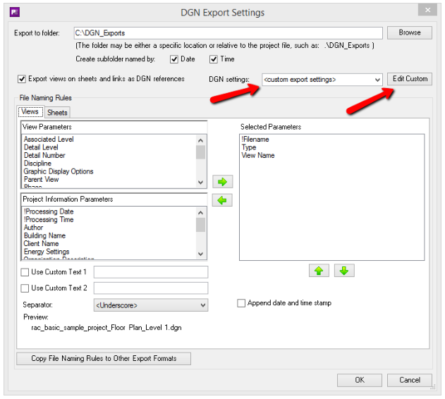
IMPORTANT:
- The DGN Settings name dropdown list is type-able. While the list will show you what is available in the currently open project, you can also freely type in whatever DGN settings name should be used during the export. This may be helpful if you plan to save this configuration and use it on other Revit project files which have that other DGN settings name already in them.
- The “`<custom export settings>`” choice is always available. When this choice is selected, the “Edit Custom” button to the right becomes available. This will allow you to edit custom DGN settings that are saved in this configuration file. The custom settings always start with default settings that will at least produce valid DGN files.
- Using “`<custom export settings>`” *has an advantage:* The export settings to use go with the Plotter and Exporter configuration file, regardless of which Revit project file is being exported. This takes the concern out of having slightly different settings defined in each project when identical outputs for all projects are desired. It also takes the concern out of things such as misspelled settings names in some projects (resulting in “settings not found” errors during the export), or having other projects where the settings desired have never been saved.
Clicking the “Edit Custom” button displays the Custom DGN Settings screen:
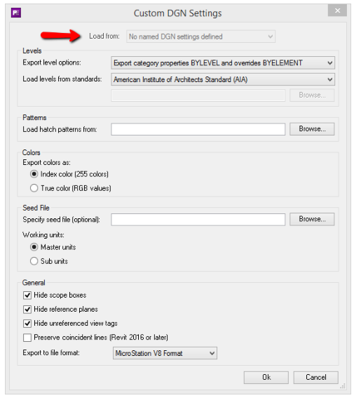
Although this project did not have saved DGN settings, if it did, the “Load from” list at the top would have been available. When selecting named settings from this list, it will ask you to confirm loading these settings from the current project AS A COPY. Once loaded they will be displayed in this dialog, and can then be edited and saved as part of the current Plotter and Exporter configuration file, which can then be applied to any Revit projects.
DWF/DWFx-Specific Settings
The settings for exporting views and/or sheets to DWF or DWFx files can be seen here:
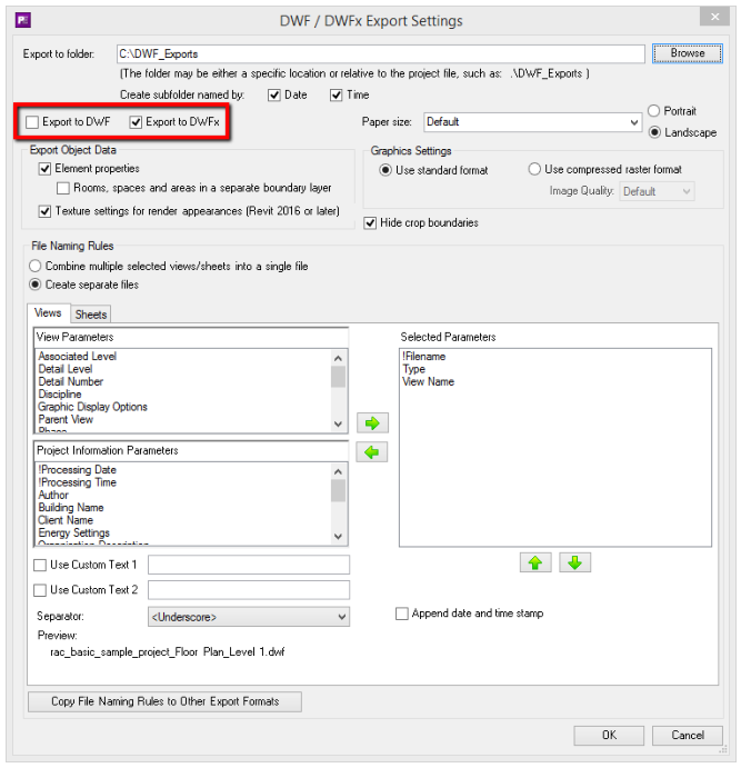
The highlighted portion in the image above shows how to turn on or off both DWF and DWFx exporting. At least one of these must be selected for the settings to be valid.
Navisworks-Specific Settings
The settings for exporting a project, or a set of selected 3D views, to a Navisworks file(s) can be seen here:
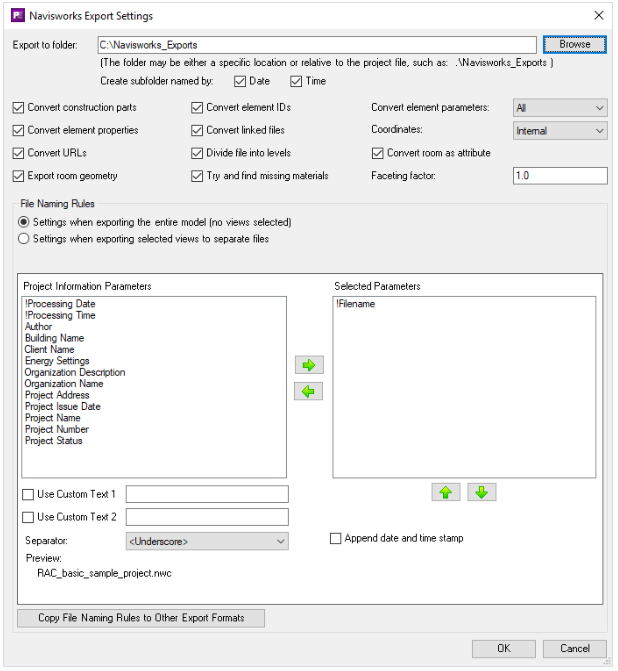
NOTE: The Faceting factor setting is only available in Revit 2020 and later.
There are different File Naming Rules settings to be used when exporting an entire model to one Navisworks file vs. exporting only selected 3D views to separate Navisworks files.
IFC-Specific Settings
The settings for exporting a project, or a set of selected 3D views, to an IFC file(s) can be seen here:
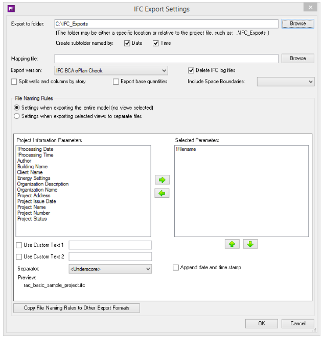
There are different File Naming Rules settings to be used when exporting an entire model to one IFC file vs. exporting only selected 3D views to separate IFC files.
FBX-Specific Settings
The settings for exporting a set of selected 3D views to an FBX file(s) can be seen here:
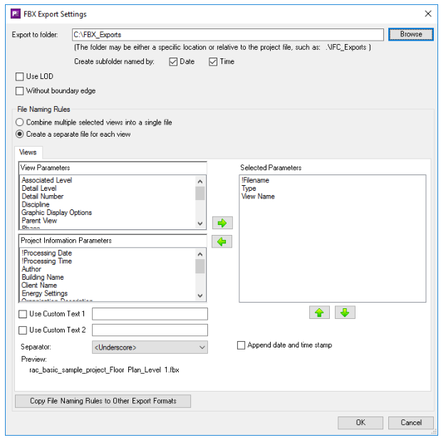
There are different File Naming Rules settings to be used when exporting an entire model to one FBX file vs. exporting only selected 3D views to separate FBX files.
CTC Model Compare-Specific Settings
Model Compare is a tool available from CTC in the BIM Project Suite. It extracts data from a project and saves it in a “snapshot” file, then can compare the differences between two snapshot files, showing how the project had changed during the time between when each snapshot file was created.
The settings for creating a CTC Model Compare “snapshot” of the project can be seen here:
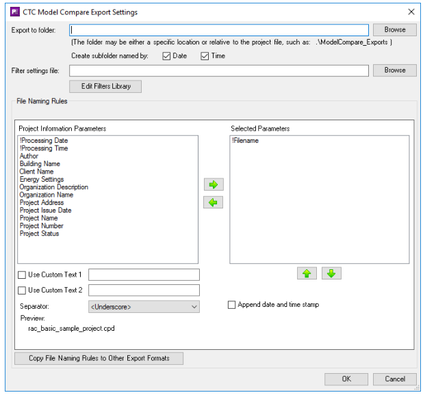
Since no views, sheets, view/sheet sets or wildcards can be dropped on the Model Compare export selection choice, the file naming rules only use project-level values.
A project snapshot filter settings file (*.psf) must be selected. This controls what data is extracted from the project and stored in the snapshot file. The default folder for filter settings files is the same folder the CTC Model Compare tool uses.
The “Edit Filters Library” button lets you create or edit filter settings files. It works exactly the same as in the Model Compare tool itself, and looks like this:
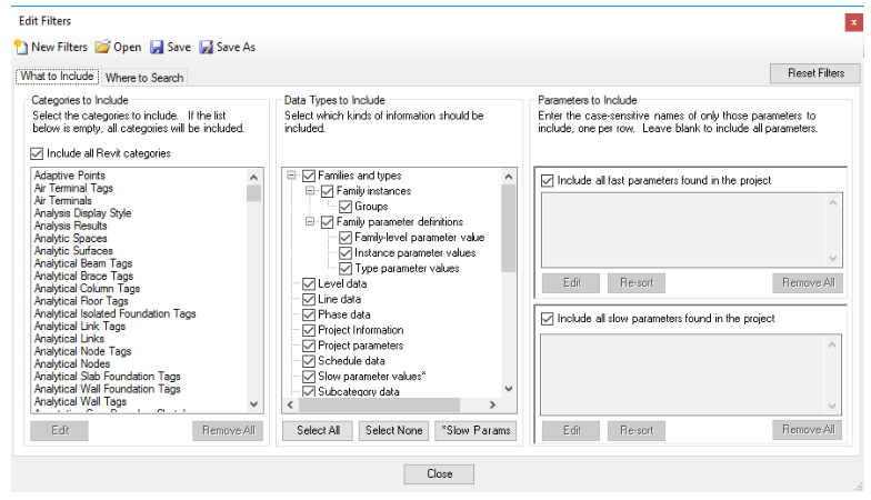
The Model Compare user’s guide explains how all of these settings work.
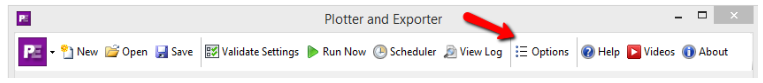
Changing Plotter and Exporter Options
You can change how Plotter and Exporter works by editing the Options. This is done by clicking on the “Options” button in the toolbar at the top of the main configuration screen:
The Options are divided into two sections: General and Email Settings Note that your system administrator may prevent you from changing either the general settings, the email settings or both.
General Options
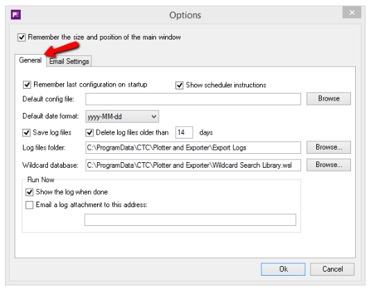
The default settings are shown above. Many of these settings are obvious, but a few deserve special mention.
If selected, “Remember last configuration on startup” will display the configuration that was last being used, even if it had not been saved to a *.peconf file.
If selected, “Show scheduler instructions” will display instructions about using the scheduler whenever the scheduler is launched. (The scheduler will be discussed below)
“Default config file” allows specifying a *.peconf file to be used whenever the “New” button is clicked in the toolbar, to start a new job. This allows automatically loading standards, such as for file naming, which PDF printer driver to use, etc. It could allow a user to only need to select the views and/or sheets to export, and everything else may be pre-defined.
For the default date format, although a list of choices is provided, you may also type in your own custom date format to use.
The “Run Now” section allows controlling the defaults that appear when the “Run Now” button on the toolbar is clicked:
Email Settings
The Email Settings tab allows specifying how to communicate with your Email SMTP server, which is needed for doing things like sending log files via email to recipients.
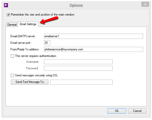
IMPORTANT:
- These settings must be configured here for the scheduler (discussed below) to also be able to send email messages. It is strongly recommended to use the “Send Test Message To:” button to send a test email to yourself to verify the email server settings are correct.
- Whenever you enter an e-mail address, you can enter multiple addresses that are separated using the semicolon character. For example:
helen@mydomain.com; adam@mydomain.com
If your email server allows sending messages from email addresses that aren’t explicitly defined on the server, and you use a non-existant “From/Reply To address,” the “From” display name on the emails may say “Plotter and Exporter”
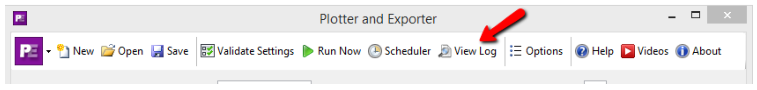
Viewing Log Files
If the General option for “Save log files” is selected, log files which list the events that happened during an export can be viewed again later by clicking on the “View Log” button in the toolbar:
Clicking this button shows the list of log files from which to choose:
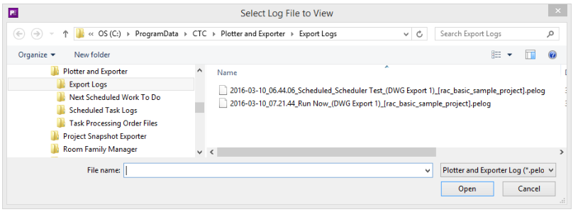
Each log file begins with a date and time stamp, followed by whether it was “Run Now” (from within Plotter and Exporter) or whether it was run using the scheduler (discussed below). For scheduled logs, the next part of the file name is the name of the task that was run at a predetermined time to do the exporting.
All logs then continue with the name of the configuration file that was used in parentheses followed by the name of the project file in square brackets.
These log files are natively stored in an XML format.
Once a log file is chosen, it reappears in the log viewer. This is an example of a log that had some errors in it:
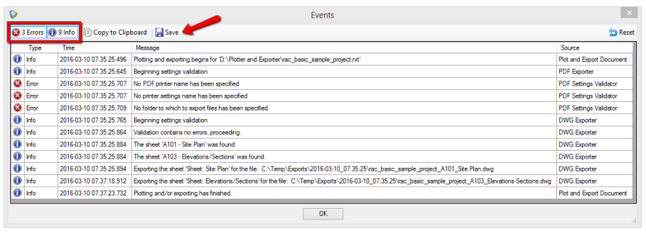
Log files can have three types of messages:
- Errors
- Warnings
- Information
The total count of each message type can be seen in the toolbar above the list. Clicking on one of those count buttons will turn the visibility for those message types on or off.
For example, clicking the “Info” button turns off the Info mesages:
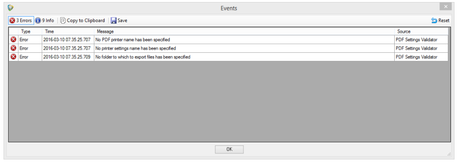
“Selected” (visible) message types have the blue outline around them, as seen above.
Log files can be saved to another location using the Save button in the toolbar. They can be saved as Microsoft Excel files, comma-delimited (csv) files, tab-delimited (txt) text files or as XML files. Only visible messages will be saved.
Log files could be mined, for example, if you want to bill back to the project the number of sheets that were plotted or exported.
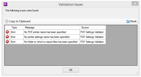
Validating Settings
This tool will show you any errors or warnings you should know about with the current settings which may prevent a successful plot or export.
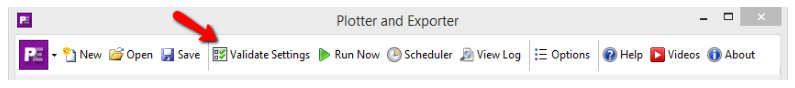
IMPORTANT: The “Validate Settings” button in the toolbar should always be used before saving a configuration file and before clicking the “Run Now” button.
Here’s an example of errors in the current settings:
Plotting or Exporting from the Currently Open Project
To apply the current configuration to the current project when only one project file is open, click the “Run Now” button in the toolbar:
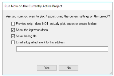
When clicked, the confirmation dialog will appear:
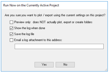
The default values for most of these settings come from the Options, as described above. If the “Preview only” option is selected, the process will continue but no plots will be made, no files will be exported and no folders specified will be created if they didn’t already exist. This allows seeing exactly what would happen without having to wait through the actual process and without having to deal with the documents generated.
IMPORTANT: For emails to work, the email server settings must be specified in the Options section.
Log files sent via email are always in comma-delimited file format (csv files). Double-clicking on a csv file will probably automatically open it in spreadsheet software installed.
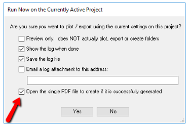
If the settings are such that PDF generation will occur, and only a single PDF file will be generated, an additional checkbox appears that allows specifying that the PDF file generated be opened in the default PDF viewer automatically when done.
Plotting or Exporting from Multiple Currently Open Projects
If more than one project file is open, the “Run Now” button in the toolbar changes to a drop-down button:
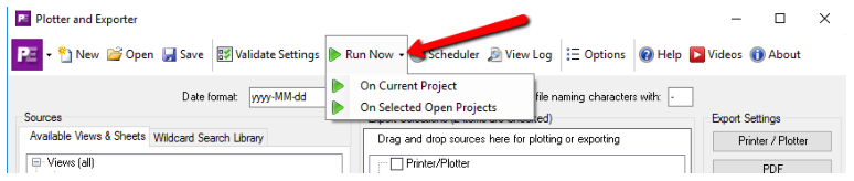
The “On Current Project” choice works the same as shown above, when only one project file is open.
The “On Selected Open Projects” choice displays a modified dialog:
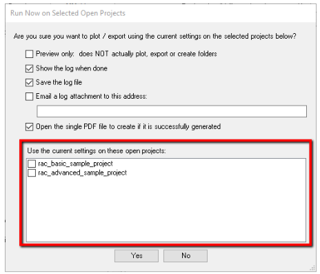
One or more projects that are currently open can be selected to have the current settings run on them. If the “Open the single PDF file to create if it is successfully generated” option is checked, multiple PDF files would be opened, up to one for each project selected.
Scheduling Plots and/or Exports to Run at a Later Time(s)
Plotter and Exporter allows scheduling a plot or export to happen in the future, with the option for it to happen repeatedly in the future.
For example, selected views and/or sheets in one or more project files can be exported to PDF files every Sunday at 6:00 PM, or perhaps every weeknight at 10:00 PM. This is done using the Scheduler button on the toolbar:

The first time you click this button, the following basic instructions will appear. Everything mentioned in these basic instructions (and much more) is explained next.
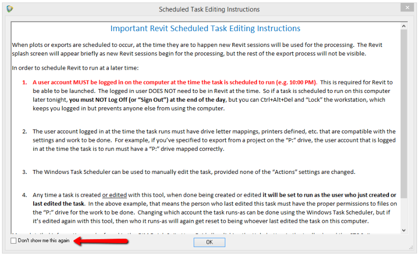
If you check the “Don’t show me this again” checkbox, this dialog won’t appear when clicking the Scheduler button in the future.
IMPORTANT:
- A BIM Batch Suite license must be available during the entire time a scheduled task runs. Plots and exports will not occur at a scheduled time if no licenses are available. When plots or exports are scheduled to occur, at the time they are to happen new Revit sessions will be used for the processing. The Revit splash screen will appear briefly as new Revit sessions begin for the processing, but the rest of the export process will not be visible.
- Scheduled plots and exports are not supported if Revit itself is using a borrowed floating license.
- A user account MUST BE logged in on the computer at the time the task is scheduled to run (e.g. 10:00 PM). This is required for Revit to be able to be launched. The logged in user DOES NOT need to be in Revit at the time. So if a task is scheduled to run on this computer later tonight, you must NOT Log Off (or “Sign Out”) at the end of the day, but you can Ctrl+Alt+Del and “Lock” the workstation, which keeps you logged in but prevents anyone else from using the computer.
- The user account logged in at the time the task runs must have drive letter mappings, printers defined, etc. that are compatible with the settings and work to be done. For example, if you’ve specified to export from a project on the “P:” drive, the user account that is logged in at the time the task is to run must have a “P:” drive mapped correctly.
- Any time a task is created or edited with this tool, when done being created or edited it will be set to run as the user who just created or last edited the task. In the above example, that means the person who last edited this task must have the proper permissions to files on the “P:” drive for the work to be done. Changing which account the task runs-as can be done using the Windows Task Scheduler, but if it’s edited again with this tool, then who it runs-as will again get reset to being whoever last edited the task on this computer.
- Central files are processed by creating a new local file in the current user’s personal temporary directory and then opening the new local file for processing. This prevents conflicts or other issues that can be caused by opening a central file directly. The new local file is created opening all worksets. When the export is complete, the new local file is closed and deleted. This workflow is needed to ensure all links (including relative links) are maintained. Single user project files can only be opened from their original locations directly, in order to ensure all links are maintained. An error will occur if the single user project file is already opened in another Revit session, either on this computer or another computer.
The Windows Task Scheduler can be used to manually edit the task, provided none of the “Actions” are changed.
It’s a good idea to test the configuration settings to be used by the scheduler manually by performing a “Run Now” on a sample project, then reviewing the log for any warnings or errors which you may be able to fix by changing the configuration settings before they are scheduled the first time. Once the Scheduler toolbar button is clicked, the list of scheduled tasks will appear:
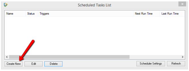
To create a new task, click the “Create New” button on the dialog seen above, which will bring up the task editor:
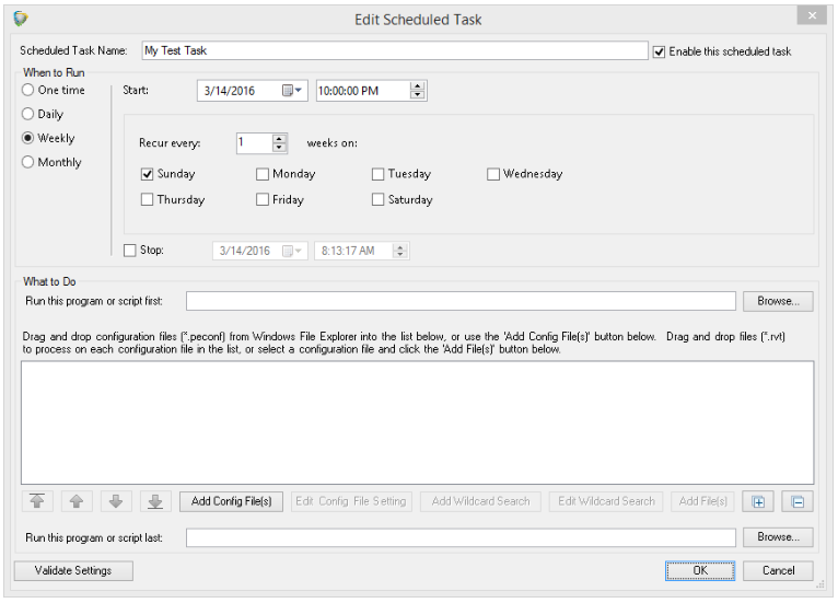 Every scheduled task needs a name and the settings to specify when it should run. These are set in the top portion of the screen, as can be seen in the image above.
Every scheduled task also needs to have defined what to do whenever the task runs. The heart of “what to do” is a list that you define of saved Plotter and Exporter configuration files, and the Revit project files on which to run each configuration file.
For example:
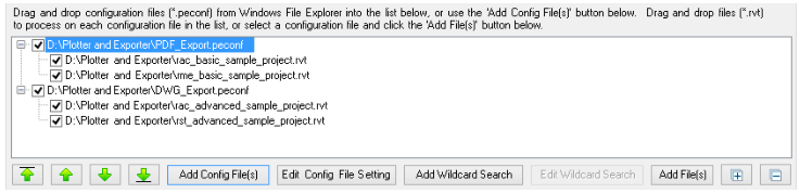
This approach allows you to specify the order in which configurations will be applied, and the order in which the projects they will be applied to are processed.
Further, this approach also lets you configure an entire evening’s processing in ONE scheduled task.
IMPORTANT: It is recommended to avoid having two scheduled tasks run at the same time on the same computer. This is mostly for performance and stability reasons. Because Revit consumes a LOT of system resources, if two or more Revit sessions are opening projects at the same time on the same computer they will compete for resources, possibly running out of memory and almost certainly running significantly more slowly than if each had all the resources available and the tasks were run consecutively.
This feature of defining all of the configuration files to be run against all of the project files in a specified order can therefore improve performance and reliability of scheduled plotting and export processing.
In the above example, we used Windows File Explorer to drag and drop configuration files (*.peconf) into the list, and Revit project files (*.rvt) onto each configuration file. This is done in the same manner as when adding views, sheets or wildcards to the Export Selections list: The new item(s) are added immediately after the item on which they were dropped.
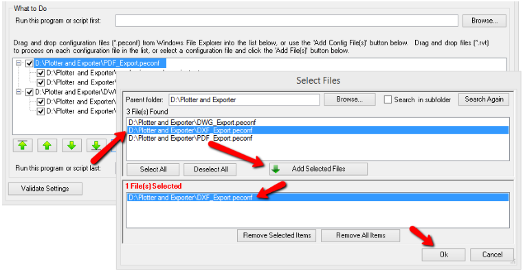
We can also use the “Add Config File(s)” button below the list to browse for one or more configuration files from one or more folders to add to the list:
Once a configuration file is in the list, Revit project files can be dragged and dropped on top of it, or the “Add File(s)” button can be clicked to use the same Select Files browser to select one or more Revit project files from one or more folders to be processed using the added configuration file settings:
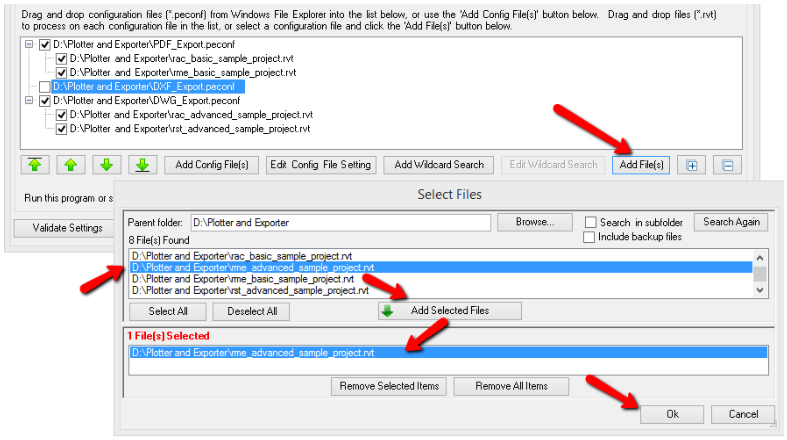
When selecting Revit project files, the search results in this dialog will not include Revit backup files by default.
Another important tool is the ability to add a “wildcard search” for Revit project files, which will search for all Revit project files whose names match a specified criteria within a given folder, and optionally all subfolders. This can be done using the “Add Wildcard Search” button below the list when a configuration file is selected. For example:
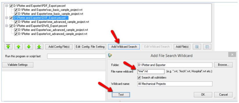
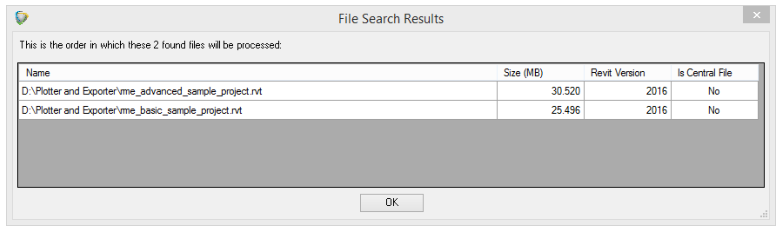
Clicking the “Test” button shows:
Editing a wildcard search that is in the list can be done by either double-clicking on the item, or selecting the item and clicking on the “Edit Wildcard Search” button or by right-clicking on the wildcard in the list and selecting “Edit Wildcard Search” from the pop-up menu.
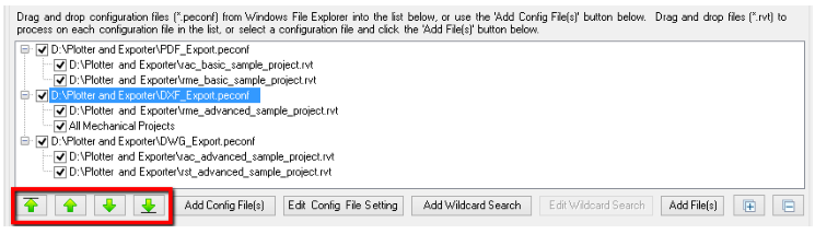
The order in which exports will be processed can be changed by using the green Move buttons below the list. This works on multiple items selected in the same manner as when adding items for export to the Export Selections list on the main screen:
Items can be removed (deleted) from the list by selecting one or more items and pressing the “Del” key on the keyboard. As is also standard for working with list items, the “Ctrl+A” key combination will select all items in the list.
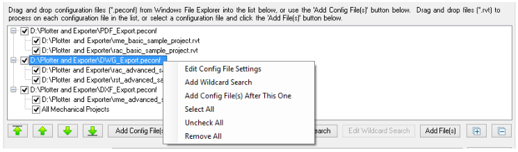
As is also the case for list manipulation in the main configuration screen, context-sensitive right-click pop-up menus are available. Here is just one example:
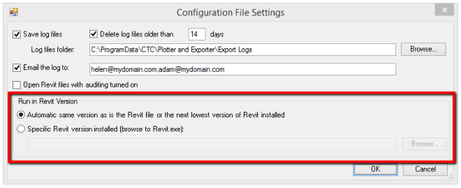
Each configuration file in the list can have custom processing settings defined. These can be edited using either the “Edit Config File Settings” pop-up menu choice, or by clicking on the “Edit Config File Settings” button located below the list, or by simply double-clicking on the configuration file in the list:
IMPORTANT: For emailing log files to work, working email configuration settings must be defined in the Options section of Plotter and Exporter. Log files are always emailed in CSV format. A single email with multiple CSV attachments will be sent to each recipient specified (separate recipient addresses with semicolon characters). Each CSV attached will be the log for a separate project file that was processed.
IMPORTANT: By default, the lowest version of Revit will automatically be run on project files based on:
- First, the version of Revit in which the project file was last saved,
then
- The lowest version of Revit installed for which Plotter and Exporter is supported
However, there may be times when you want to force the projects to be processed in a specific (same or later) version of Revit. For example, if a new version of Revit supports a new export format such as a new version of the DWG or IFC formats. To facilitate this, you can select “Specific Revit version installed (browse to Revit.exe)” and then select which Revit.exe to run.
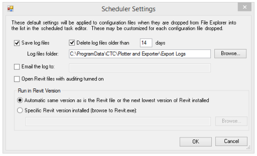
The default settings to apply to configuration files as they are added to the list can be controlled back on the main Scheduled Tasks List window using the “Scheduler Settings” button, which will be demonstrated further below.
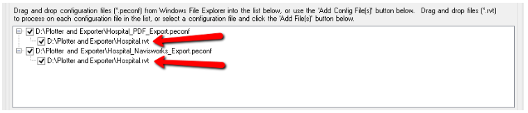
A workflow where using different configuration file settings may be useful is if some project files should have their logs emailed to one person, while other project files should have their logs emailed to another person. For example:
In this example, the same configuration file is listed twice, with different project files to be run for each one. The only difference in this case is to whom the emails are sent for each list of projects processed. As is the case throughout Plotter and Exporter, multiple email addresses can be listed if they are separated with a semicolon (;) character. For example: helen@mydomain.com; adam@mydomain.com
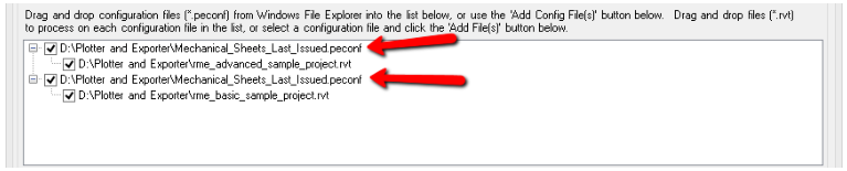
Another scenario where this may be useful is if Helen should get the PDF export logs and Adam should get the Navisworks export logs. This can be done by specifying the same project file for two different export configurations:
IMPORTANT: A separate Revit session is launched for each project file in the list, even if the same project is listed under different configurations. After each project is processed, its dedicated Revit session is closed. This is done because:
- A different version of Revit may need to be used for each project processed (e.g. if the default autodetection setting is used)
- A different, specific version of Revit may be set up for each configuration file
- To help ensure a clean Revit session is used for each project
Other programs or scripts can be run before and/or after the project file processing. For example:
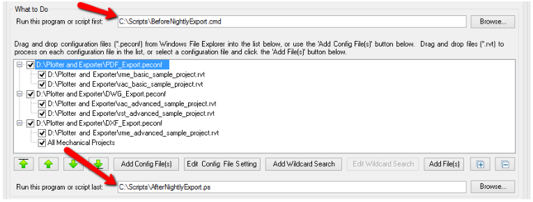
The script that runs before processing may, for example, delete old export files if the new ones will be going in the same folders.
The script that runs after processing is done may, for example, zip up the exported files and store the zip file somewhere else.
In the lower left corner of the task editing window is the Validate Settings button. This button works just like the same toolbar button in the main Plotter and Exporter configuration window, only it applies to the scheduled task definition. For example:
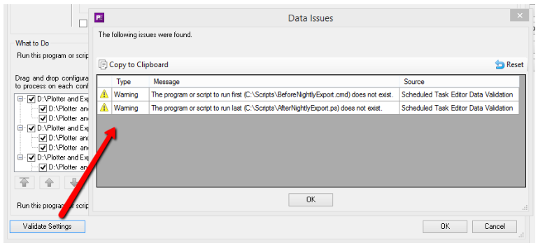
Finally, the last item to mention on the task editor screen is the task enable checkbox, which is checked by default:
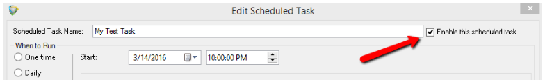
A scheduled task can be quickly and easily enabled or disabled by changing this checkbox. Disabling the task will prevent it from running at the scheduled time without having to delete its entire definition. So the task can be “turned on” or “turned off” easily.
Clicking the “OK” button at the bottom of the list saves the task definition in the task list:
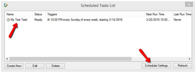
Editing a task can be accomplished by either double-clicking it or by selecting it and either clicking the “Edit” button below the list or right-clicking on it and selecting the “Edit” choice from the pop-up menu.
The “Scheduler Settings” button below the list can be used to change the default values that are applied to configuration files as they are added to the list for processing:
Troubleshooting Tools
The primary tools for troubleshooting issues are the log files. These can be found in the following locations:
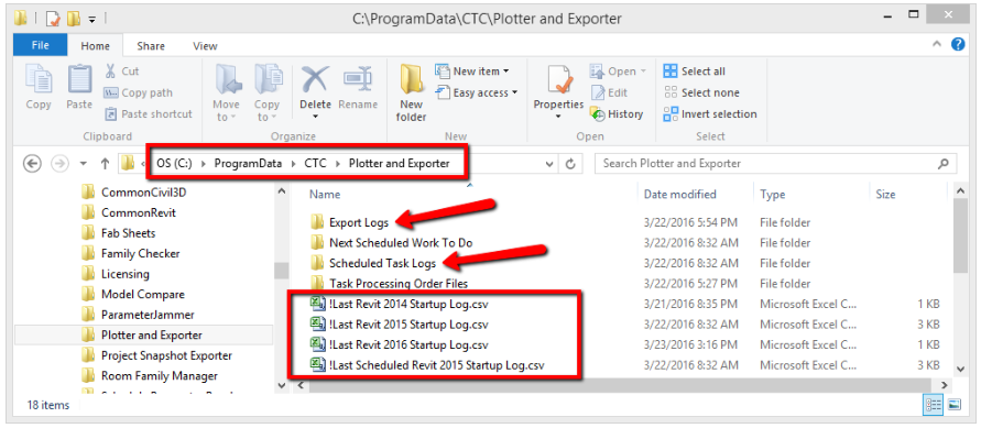
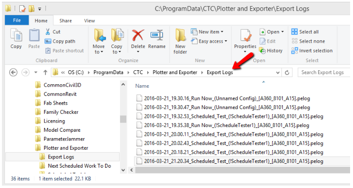
The “Export Logs” folder contains the “pelog” files which have information about the actual export process from a Revit project. For example, they’ll list which views or sheets were found, the locations and filenames of files generated, etc. Pelog files are in XML format, and are really only viewable in the Plotter and Exporter tool directly.
This is why all e-mailed log files are sent in comma-delimited (CSV) file format, so they may easily be opened and read in a spreadsheet program, such as Microsoft Excel, and do not require even having Revit installed to be able to be read.
The files in the Export Logs folder may be from either the “Run Now” (manual) exports or the scheduled task (automated) exports.
The “Scheduled Task Logs” folder contains CSV files which are from the task scheduler. These logs contain information such as each of the configuration files and each of the project files being processed, the project files as they were found by the wildcard search, when and which version of Revit is launched for opening and processing each project file, etc.
The “!Last Scheduled Revit 201x Startup Log.csv” files contain information generated when Revit starts up after the last time it was launched by the scheduler. These logs show what Revit did on startup, such as to where it copied a central file temporarily for opening as a new central file for processing, and other information about the processing that occurred within Revit as a result of the scheduler launching Revit.
The “!Last Revit 201x Startup Log.csv” files contain information generated the last time Revit started up, whether or not it was started by the scheduler. Most of the time these files report there’s no work for Plotter and Exporter to do, but the information will match the information found in the last scheduled startup log file if the scheduler was the last thing to launch Revit.
These logs can contain important information, for example if there’s a general problem with the Plotter and Exporter such that it will never plot or export information until that general problem is fixed.